
Many people have found the porting guide to be helpful — it walks you through porting Pixy to a new controller including code examples:
http://cmucam.org/projects/cmucam5/wiki/Porting_Guide
thank you,
I already realized all this starting at “serial protocol”
http://cmucam.org/projects/cmucam5/wiki/Porting_Guide#The-serial-protocol
- but I honestly don’t understand a single word. This is far too low-level and high-tech.
I don’t even know what a frame is and why to count 10 or 50 or what getword or back-to-back or sync or g_blocktype are needed for or why I have to fiddle around with little endians (I heard of it, but nevertheless that’s not the programming skill I’m used to).
What I understand is just
typedef struct
{
  uint16_t signature;
  uint16_t x;
  uint16_t y;
  uint16_t width;
  uint16_t height;
  uint16_t angle; // angle is only available for color coded blocks
} Block;
anything else is far too complicated. I’m not interested in frames and syncs and endians or indians.
I would need a high level API just like by hello_world.ino, but more detailed about sorting of signatures and colorcodes.
I’m not interested in how the cam or the serial interface works, I just want to poll and sort blobs (blocks) and want to track them in case they are moving.
Maybe a tutorial providing some sceen shots of the cooked video of PixyMon, showing some colored objects and some ColorCodes.
And then showing the related data which come in to Arduino by which order of colorID and colorcode and size and location using a function just like in hello_world.ino repeatedly.
Hi Helmut,
The hello_world example is the best place to start (that’s why it’s called hello world!) You just plug Pixy into your Arduino and run it. Start there! Take this program and modify it. You don’t need to understand any protocols to use it and you don’t even need to be a skilled programmer to understand what it’s doing.
Still, there are some notes about its code structure here:
http://cmucam.org/projects/cmucam5/wiki/Hooking_up_Pixy_to_a_Microcontroller_(like_an_Arduino)
If you have specific questions about the hello_world program, please ask them. It’s likely that you aren’t the first person with these questions, so ask, but try to be specific.
Look at the output of hello_world. Teach Pixy some color codes, notice how the output changes. Change some config parameters (like the color code mode) and see how the output changes…
I’m not sure what your setup is — you are using an Arduino, I know that, but you’ve been asking questions about getting multiple Arduinos communicating over SPI. This is more complicated! If you are uneasy about programming, tackling these more advanced use cases (like multiple pixys) is probably going to be overwhelming. Start simple!
thanks!
no, I’m not using many Arduinos all at once - why do think I’d do?
Of course I started by hello_world: I mentioned that several times!
But I can’t clearaly see, at what time I’m receiving signature data and when - which - colorcode data.
Addionally there seem to be cc issues about the current FW.
this is my code - it displays the block data on a local TFT .
Just tell me how to insert 1 line or 2, how to identify cc IDs and cc (x,y) block positions:
// pixy-cam LCDTFT monitoring program
// pixyTFTSPI
// Pixy Cam connected by SPI
// version 0008

#include
#include
#include

// UTFT myGLCD(Model,SDA,SCL,CS,RST,RS)
// adjust the model parameter to suit the display module!
UTFT     myGLCD(QD220A,43,42,41,0,40);
extern   uint8_t   SmallFont[];
uint8_t    ScrRatio;

Pixy pixy;

void setup()
{

  myGLCD.InitLCD();
  myGLCD.setFont(SmallFont);

  pixy.init();
  //pixy.blocks[i].x The x location of the center of the detected object (0 to 319)
  //pixy.blocks[i].y The y location of the center of the detected object (0 to 199)
  // Pixy_maxSize/(GLCD_maxSize-frame)
  ScrRatio=max(320/(myGLCD.getDisplayXSize()-20), 200/(myGLCD.getDisplayYSize()-20) )+1;

  myGLCD.clrScr();
  Serial.begin(19200);

}

uint16_t sigcolor( uint8_t signature) {  // <<<<<<<<<<<<<<< customize !! <<<<<<<<<<
  uint16_t color;
  if(signature==1) color=VGA_RED;      // light red
  else
  if(signature==2) color=VGA_AQUA;     // light blue
  else
  if(signature==3) color=VGA_YELLOW;   // just yellow ;)
  else
  if(signature==4) color=VGA_LIME;     // light green
  else
  if(signature==5) color=VGA_FUCHSIA;  // light pink
  else
  if(signature==6) color=VGA_BLUE;     // dark blue
  else
  if(signature==7) color=VGA_PURPLE;   // dark pink
  else
  color=VGA_WHITE;
  return color;
}

char sbuf[240];
#define maxblocks  64
uint8_t    blockS[maxblocks];
uint8_t    blockX[maxblocks];
uint8_t    blockY[maxblocks];
uint8_t    blockW[maxblocks];
uint8_t    blockH[maxblocks];

void loop()
{
  static int i = 0;
  int j;
  uint16_t   nblocks;
  uint8_t    x1,y1,x2,y2;

  nblocks = pixy.getBlocks();

  if (nblocks)
  {
    i++;

    if (i % 10==0)
    {
      myGLCD.clrScr();
      sprintf(sbuf, "Detected %d:\n", nblocks);
      Serial.print(sbuf);
      for (j=0; j<min(nblocks,maxblocks); j++)
      {

        sprintf(sbuf, "  block %d: ", j);
        Serial.print(sbuf);
        pixy.blocks[j].print();

        blockS[j]= pixy.blocks[j].signature;
        blockX[j]= pixy.blocks[j].x;
        blockY[j]= pixy.blocks[j].y;
        blockW[j]= pixy.blocks[j].width;
        blockH[j]= pixy.blocks[j].height;

        myGLCD.setColor(sigcolor(blockS[j])); myGLCD.setBackColor(VGA_BLACK);
        x1=blockX[j]-blockW[j]/2;
        x2=blockX[j]+blockW[j]/2;
        y1=blockY[j]-blockH[j]/2;
        y2=blockY[j]+blockH[j]/2;
        myGLCD.drawRect(x1/ScrRatio, y1/ScrRatio, x2/ScrRatio, y2/ScrRatio );

        sprintf(sbuf, "%d", blockS[j]);
        myGLCD.print(sbuf, (x1+10)/ScrRatio,(y1+10)/ScrRatio);

      }
    }
  }
}
I’m not aware of any color code issues with the current firmware (please describe).
It sounds like you are asking how to tell regular blocks from color coded blocks? Sorry — I’m still having trouble understanding what your question is… posting your code without any other comments is not helpful!
The color code blocks have signature numbers greater than 7, ie
if (blocks[j].signature > 7)
serial.println(“color code block!”);
else
serial.println(“regular block!”);
yes I want to seperate signatures from CCs.The problem is that you haven’t documented these details unequivocally in any code example besides hello_world.ino.
Anyone posted that signature 7 don’t work.
ok, if CCs have signatures >7 then signature 7 is no issue.
I think my question should be easy to be understood -
my code displays the block data on a local TFT .
Just tell me how to insert 1 line or 2, how to identify cc IDs and cc (x,y) block positions!
I’d need a function to decode the CC number into the 2 related colors and the concerning stored CC ID (I don’t understand this “octal” thing and what I’ll get as a result).
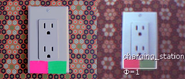
And I want to detect them by position (x,y) and by it’s CC number when a CC is detected like in this foto:
!http://i74.photobucket.com/albums/i241/cmucam/cc_zps767834e4.jpg!
In PixyMon I can see there are 7 “codes” to store color codes, just like 7 signatures to store colors.
And now imagine I have multiples of either CC and multiples of different CCs.
Unfortunately you don’t provide a guide and code how to define, how to retrieve and how to handle these CC data e.g. in order to display them on a local display and make them appear like on the PixyMon screenshot above.
Helmut, you are asking people to write code for you. Stop that!
“Just tell me how to write 1 or 2 lines of code!” — you are commanding us to write code, but nowhere did I see an offer of cookies or brownies! At least Cindy in Intro to Programming baked me cookies— and she was a lot more attractive…
Ask us a question sir!
I’m guessing — your question might be “Could you give me an example of what a signature number would be for a color code consisting of signature 1 and signature 2 put together (for example)?”
Sure —
It would be a base-8 (octal) number of 12. (the 1 representing signature 1 and the 2 representing signature 2).
How do I convert base-8 to base-10, so I can look for this signature in my code?
Check out this site:
http://www.rapidtables.com/convert/number/octal-to-decimal.htm
(so look for signature number 10 in your code.)
Helmut, when you write another message on this forum, please make sure you are asking a question!
thanks!
OMG if we only had a German forum!
of course I know how to convert octal to decimal - but I do not know what to do with the numbers!
I wrote “I don’t understand this “octal” thing and what I’ll get as a result” - I mean by that that I don’t know what the octal results are all about! How do I have to handle the octal numbers? or the decimal? or what ever???
My English is poor, I know, Google translate often does not help!
I have no I dea how to use code for CCs because you dont provide code for CCs!
You said I should look at your effing hello_world.ino, but I’m already using this code, I have already incorporated it into mine!
Just look at my code, it’s exactly helloworld, but a little more extended!
Give me good exampleas of your own and everything would be fine!
Otherway round, when you don’t have own code to explain things, show me how to change my code and show me what I will get!
Your tutorials are lousy, make better ones! I don’t see any explanations about CCs and I don’t understand a word!
Sorry Helmut – no one here speaks German.
Where did you purchase your Pixy? Assuming it was a German distributor, they might be able to help – that’s part of the agreement we have with our distributors — they provide product support with native speakers.
Trying to learn a technical topic in a foreign language (like you are doing) doesn’t sound like fun… so reach out to them. (please) This dialog is not progressing.
ok, it was Watterott Elektronik in germany, but I already asked them about SPI SS/CS mode and they couldn’t help me.
So they are not supposed to help me by this CC thing.
I meanwhile observed that already the Set CC Signature procedure does not work correctly.
I have a test screenshot 0
Here you see a book with a red bar and just at it’s right side there is a green bar.
The CC area is the whole red bar plus the directly adjacent green bar.
So the ColorCode which I marked by Set_CC_Signature_1 is the whole area of red bar + green bar.
If I do it I get the screenshot 1 - just unusable. What is going wrong?
screen shot after setting CC signature 1:
Ah, the color codes make an assumption that the color code markers (swatches, whatever you want to call them) are roughly the same size (between 50 and 200% of each other) It’s a constraint that reduces false positives.
Your object is not going to work because the green area is much much bigger than the red line.
Hope this helps!
quote:“Your object is not going to work because the green area is much much bigger than the red line.”
sorry, you’re wrong!
(besides, you didn’t mention this important detail at any place in your descriptions so far! )
But:
the red bar is almost of the same size as the dark green bar at it’s right side.
But even if I’m marking a rectangle in PixyMon as a subset of the whole 2-bar-area which is exactly half-red and half-green then it also does not work. afterwards the PixyMon screen looks exactly the same as on foto_1
Helmut, you’re making this too complicated! The API documentation is straightforward because the API is really simple! (two calls, init and get)
There is no colorcode field, you can tell if the block is a color code by looking at the signature number.
So— for example, if you want the position and angle of a color code with signatures 1 and 2 put together, just do this
if (pixy.blocks[j].signature==10) // 10 = 12 octal, but change number to whatever CC you want to detect!
{
   // position of this CC is pixy.blocks[j].x, pixy.blocks[lj].y,
   // angle is pixy.blocks[j].angle
}
Regarding the red rectangle, etc, try playing with color codes similar to ones in this video
ie. squares and rectangles of roughly the same size.
it’s hard for me to understand what you are doing in your video because I can’t detect what you are doung on your computer.
A written pictured tutorial with detailed little steps would be appriciated.
As I already wrote:
I still have absolutely no clue how you are coding, storing, decoding, and retrieving color codes.
I don’t even understand the rough concept behind “colorcode” by geometry, mathematics and coding.
http://cmucam.org/boards/9/topics/5253?r=5263#message-5263
does it mean I first have to train the single colors and then by either obscured way have to teach what single colors have to be composed to a color code?
what do you mean by
// 10 = 12 octal, but change number to whatever CC you want to detect!
what does 12 octal stand for? 7 plus 5 ?
in case, yes: what is 7? what is 5?
or does it mean 1 plus 2 ?
in case, yes: what is 1? what is 2?
or what else?
i.e., by which mathematical formula do I get the single parts of the octal number?
and what exactly do the single parts of the octal number represent?
Please explain more detailed how to work with color codes, starting off by Zero.
Maybe these misunderstandings are the reason why I never get results by Arduino Code to retrieve CC data.
Helmut,
Each octal digit is one color code ID. For example if in pixymon, you defined CC 1 to be a red blob and CC 2 to be a green blob, getting an octal 12 means that Pixy has detected a blob with red and green adjacent. If you had also defined color code 3 to be yellow, an octal 132 means that Pixy has detected a blob of Red next to Yellow next to Green.
Because of the complexity that can arise from the possible number of combinations and of separating each octal digit, I recommend figuring out the color sequences you are interested in (for example RG, RGY, RYG) and the octal values (continuing the example 12, 123, 132). Then convert them to decimal, and have your program only look for those values when checking for color codes.
Hope this helps,
Tom
oh - does that mean that you have to define CC colors singularily? I always thought that a CC is the whole area consisting of 2 colors side by side…
If there only was a reasonable tutorial!
So Pixy combines all define single CC colors by itself to all permutations of all single ones?
3 defined colors would cause Pixy to detect
1+2
1+3
2+3
1+2+3
and even
2+1
3+1
3+2
2+1+3
3+2+1
1+3+2
…
and so on, side by side?
Based on tests I ran, that is what I saw.
But you will not get mirror images reported as 321. That would be reported as 123 with angle shifted 180 degrees.
You would get
12
13
23
123
132
213
I’m not sure if you would get 121, 212, 131, 232, 313, 323 assuming you had those 3 colors adjacent like in your earlier photo (but with more equal swatches).
Originally I tried defining groups of colors, and it seemed to work, but the results were screwy. When I read the wiki a few times, it seemed that the single color made sense and my data supported that.
So you can see that the more colors you define, how complex the results can be (especially if codes like 121 are possible.)
Tom
If you look in the Using Color Codes wiki article you can see a simple example.
Four colors for color codes are defined using Lego blocks. See the pictures in the article.
Blue is 1, Green is 2, Red is 3, and Blue is 4.
The last photo of the article shows the pixymon screen with 4 stacks of blocks. Above each block is the color code signature.
The left set of blocks is YGRB (1234), the upper center stack is BY (21 which is reported as 12, I’m not sure I understand the angle on that one). The bottom center is GYR (213), and the one on the right is YGR (123).
I think that some of the confusion is because “color codes” seems to be used for each individual color (color code signature) and the color group (color code).
Tom
yes, thank you, now your posts really helped me a lot to understand!
I always thought that “color code” is the whole colored pattern by either predefined color-combination that I have marked before.
I never understood that I had to train single colors, not the whole combined pattern thing!
And that it’s not allowed to have patterns like 1-2-1 was also new to me
(- anyway, by origin the 2 green colored areas right- and left-hand of the red bar are completely different but nevertheless the cam does not detect the difference.)
So that’s now enough information for me to start working with it. I’ll keep you informed…
thanks again!
